flex PCB manufacturing
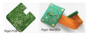
If you have a design that requires flexibility, then your choice of PCB materials and construction will be key to a successful product. Flexible circuits and rigid-flex circuits are multilayer structures with a flex ribbon connecting rigid sections of the board to allow traces to be routed across the ribbon. The conductive elements of the flex are usually made from copper, which is printed on top of an insulating film. Conductor traces are designed to be as thin as possible in order to minimize stress, while still allowing adequate power delivery and signal integrity.
Choosing the right flex materials can reduce your manufacturing costs and lead times. You can use standard rigid FR-4 material for the rigid section of the board, and then choose from a variety of different flex materials, copper thicknesses, and constructions. Common flex designs utilize a combination of 1 or 2 mils of polyimide with 1/2 oz or 1 oz copper. This will save on materials and help you keep your flex design within budget.
In addition to the base laminate, you will need to choose an adhesive for your flex pcb. There are a variety of options, including acrylic and epoxy adhesives. You may also choose to use a protective finish such as solder mask, coverlay, photo-imaged dry film, or liquid photo-imaged polymer. These finishes will protect your board from damage during handling, provide a solderable surface for components, and prevent copper migration due to high-temperature conditions.
What materials are commonly used in flex PCB manufacturing?
The dielectric used in your flex circuits is another important factor to consider. PI (polyimide) substrates are typically preferred in flex circuit applications due to their toughness, resistance to movement and vibrations, and temperature stability. The insulating properties of PI also make them highly tolerant of repeated solder reflow cycles and thermal cycling.
To improve the performance of your flex circuit, you should also pay attention to your etching and plating processes. You should prefer panel plating that spreads copper throughout the entire substrate, rather than button plating that applies copper solely to pads. This allows for more precise copper thickness and width control, as well as better regulated impedance at higher speeds.
Conductor traces on your flex circuit should be oriented parallel to the overall bend radius, rather than at sharp angles. This will prevent stress concentrations on the traces that can cause failure due to bending. It’s also a good idea to taper down the traces as you move from thicker to thinner areas of the board to avoid bending stresses.
Flex PCBs are subject to intense mechanical and environmental stresses during assembly, test, and transportation, so they must be constructed with the highest-quality materials. When you use a reliable PCB manufacturer, your project will be built with materials that will stand up to the demanding environments in which they’ll operate. Be sure to discuss your material choices with your fabricator, and ask for detailed fabrication drawings that show each layer of the flex section.